A gear pump relies on a change and movement of the working volume formed between the pump body and the meshing gear to transfer or pressurize the rotary pump.
The structure of the externally engaged double gear pump. A pair of intermeshing gears and pump cylinders separate the suction chamber from the discharge chamber. When the gear rotates, the volume between the teeth at the side of the suction chamber side is gradually increased, the pressure is lowered, and the liquid enters the tooth under the pressure difference. As the gear rotates, the liquid between the teeth is brought to the discharge chamber. At this time, the volume between the teeth at the meshing side of the discharge chamber side is gradually reduced, and the liquid is discharged. The gear pump is suitable for conveying lubricious liquids that do not contain solid particles, are non-corrosive, and have a large viscosity range. The pump can flow up to 300 m3/h and pressures up to 3 x 10⁷ Pa. It is commonly used as a hydraulic pump and for conveying a wide range of oils. The gear pump is simple and compact in structure, easy to manufacture, easy to maintain, and self-priming, but with large flow and pressure pulsations and high noise. The gear pump must be equipped with a safety valve to prevent damage to the pump or prime mover due to some reason such as clogging of the discharge pipe causing the pump outlet pressure to exceed the allowable value.
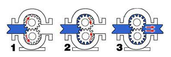
Gear Pump Working Principle
In the terminology, a gear-type asphalt pump is also called a positive displacement device, that is, a piston in a cylinder, and when one tooth enters the fluid space of the other tooth, the liquid is mechanically squeezed out. Because the liquid is incompressible, the liquid and the teeth cannot occupy the same space at the same time, so that the liquid is eliminated. This phenomenon occurs continuously due to the continuous engagement of the teeth, thus providing a continuous discharge at the pump outlet, which is the same amount per revolution of the pump. As the drive shaft rotates uninterrupted, the pump discharges fluid without interruption. The pump flow is directly related to the pump speed.
In fact, there is a very small amount of fluid loss in the pump, which makes the pump’s operating efficiency not reach 100%, because these fluids are used to lubricate both sides of the bearing and the gear, and the pump body can never be fitted without clearance. The fluid cannot be discharged 100% from the outlet, so a small amount of fluid loss is inevitable. However, the pump can still operate well, and for most extruded materials, it can still achieve an efficiency of 93% to 98%.
For fluids with varying viscosities or densities in the process, such pumps are not affected too much. If there is a damper, such as a strainer or a limiter on the discharge side, the pump will push fluid through them. If the damper changes during operation, ie if the filter is dirty, clogged, or the back pressure of the limiter increases, the pump will maintain a constant flow until the mechanical limit of the weakest part of the device is reached. (usually equipped with a high viscosity pump torque limiter).
There is actually a limit to the speed of a pump, which depends mainly on the process fluid. If the food oil is delivered, stainless steel gear pump can rotate at a very high speed, but when the fluid is a high viscosity polymerization This limitation is greatly reduced when the melt is melted.
It is very important to push the high-viscous fluid into the two-tooth space on the side of the suction port. If this space is not filled, the pump can not discharge the accurate flow rate, so the PV value (pressure × flow rate) is another limiting factor, and Is a process variable. Due to these limitations, gear pump manufacturers will offer a range of products, ie different sizes and displacements (amounts discharged per revolution). These pumps will be matched to specific application processes to optimize system capacity and price.
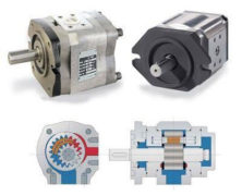 Gear pump classification and structure characteristics